Technical parameters:
----------------------------------------------------------------------------------------
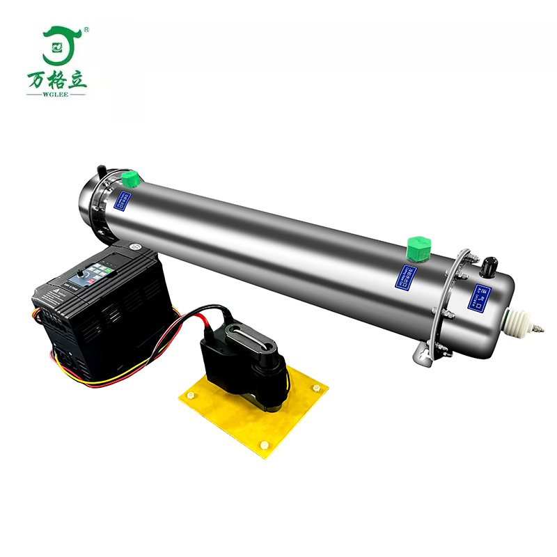
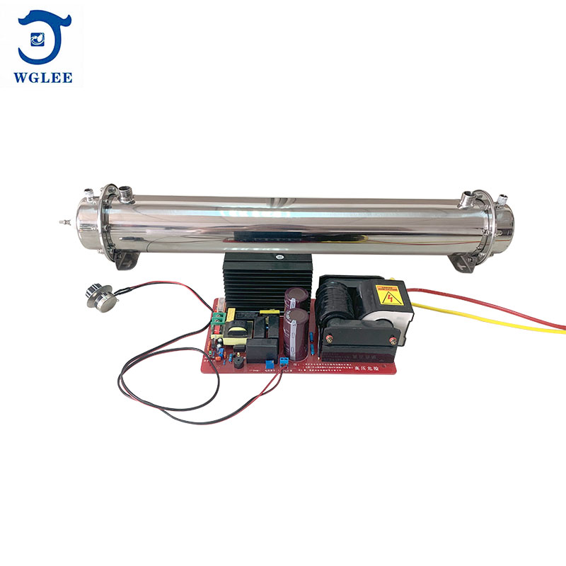
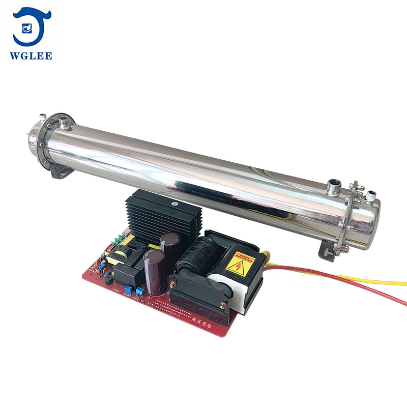
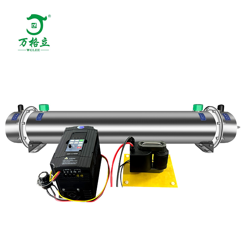
Name: cellular 50G/H ozone generator accessories (ozone converter+high voltage package+ozone tube)
Type number: FW-50G
Working voltage: AC220V/50HZ.
Effective power consumption: 50 ~ 400W adjustable
Operating current: 3A
Output voltage: 4KV
Output frequency: 5500-7000HZ
Frequency converter size: 145*90*110mm, hole spacing 130*75mm,φ4mm.
Transformer size: 130*110*100mm, hole spacing 110*90mm,φ5mm.
Ozone tube size: 700*140*140mm, hole spacing 520 * 44mm, φ 5.2mm.
Size of water inlet: 1/2 external thread
Water outlet size: 1/2 external thread
Air inlet size: 1/4 external thread
Air outlet size: 1/4 external thread
Air source: air or oxygen.
The air flow rate is 70-90L/min and the oxygen flow rate is 10L/min.
Environmental temperature requirements: 5 ~ 40℃,
environmental humidity requirements: ≤85%RH.
Cooling water requirements: water temperature < 35℃ and pressure < <0.2Mpa.
Special note: The cellular ozone generator itself is a capacitive load. When the gas source pressure is different, the capacitance is different, and the power will change according to the change of the capacitance. Therefore, under different gas source devices, it is necessary to adjust the frequency or pulse width of the power supply to control the power output of the power supply, so as to avoid the power supply burning caused by insufficient ozone concentration and output or power exceeding the rated power value.

Wiring diagram-------------------------.
Note: the terminal command has been set in the factory, and it is only necessary to connect them according to the above diagram when assembling.
F13:02 Frequency adjustment (0-10KHZ)
F01:01 Voltage adjustment
[Frequency/voltage adjustment can change the operating power/current, which has been set at the factory under no-load condition. If the operating power/current needs to be adjusted due to different field conditions, the manufacturer should be contacted for adjustment.]
Frequency adjustment method of ozone inverter;
1. Press "ESC" to display "Fxx" in the main interface.
2. Press the up or down arrow key to "F01" and then press "ENTER".
"F01:00" appears, and then press the up key to 01, and "F01:01" will be displayed.
3. Press the "ENTER" key to display the current frequency value in the main interface.
4. Press the right arrow key until "100 or 10 digits" flashes, press the up or down key to increase or decrease on the basis of the original frequency value, and then press "ENTER" to confirm.
5. Press "ESC" to exit the main interface.
Adjustment method of voltage value of ozone inverter;
1. Press "ESC" to display "Fxx" in the main interface.
2. Press the up or down arrow key to "F13" and then press "ENTER".
"F13:00" appears, and then press the up key to 02, and "F13:02" will be displayed.
3. Press the "ENTER" key and the current voltage value will be displayed in the main interface.
4. Press the right arrow key until "one or ten digits" flashes, press the up or down key to increase or decrease the original voltage value, and then press "ENTER" to confirm.
5. Press "ESC" to exit the main interface.
(The high-voltage package is installed on the insulation board, and the peripheral edge is more than 10cm away from the metal plate, so the heat dissipation should be done inside the box.)
installation instructions
Step 1: the ozone power supply and high-voltage package are installed on an insulating plate (non-conductive material, with a thickness of more than 5MM), which is fixed in the chassis. It should be noted that the periphery of the high-voltage package is more than 20 cm away from the metal chassis shell (if the high-voltage part is too close to the metal chassis shell, it may form a high-voltage vortex, which may affect the use or even damage), and the high-voltage package needs convection air to dissipate heat (fan to dissipate heat). The discharge chamber is installed inside the chassis and can be connected with the chassis shell. The high-voltage line is connected to the terminal of the discharge chamber, and the high-voltage ground wire is connected to the shell of the discharge chamber. Note that the high-voltage line needs to be more than 2 cm away from other lines or cabinets, and it is not allowed to touch.
Step 2: Installation of cooling water: If the discharge chamber is installed parallel to the plane, water can enter or exit at any end; if the ozone tube is installed perpendicular to the plane, the high-voltage line connector needs to face directly above, with the water inlet at the lower end and the water outlet at the upper end. Check that no water leakage is allowed after the water pipe is connected. The cooling water can be circulated or externally cooled, which is convenient for installation.
Step 3: Installation of air inlet and ozone outlet: an air nozzle close to the high-voltage terminal is an air inlet, and the air guide pipe of the air inlet is made of common materials such as silica gel and PVC, and the air outlet must be connected with anti-oxidation materials (tetrafluoride pipe, fluorine hose, stainless steel pipe, etc.), so as not to leak. The gas, whether oxygen or air, introduced into the discharge chamber should be clean and dry, and the temperature should not be higher than 35 degrees, and the dew point should be ensured.
Step 4: Installation of potentiometer. The potentiometer is installed on the control panel of the chassis shell, which is convenient for users to adjust and use. Its main function is to adjust the output power of ozone power supply, so as to change the concentration and output of ozone output. Turn it clockwise to jump up and turn it counterclockwise to turn it down.
Step 5: Check the wiring: After connecting the high-voltage wire and the high-voltage ground wire to the ozone tube, try to connect the high-voltage wire with the shortest distance. When the accessories leave the factory, the high-voltage wire is about 50CM long, so as to avoid the high-voltage wire from touching other wires or objects in the cabinet. It is best to install and use silicone tube or PCV sleeve wire independently. Other lines, especially the digital display electronic device connection line and the on-line signal detection connection line, should not be close to the high-voltage part (high-voltage package, high-voltage line, ozone tube), otherwise high voltage may interfere with its normal use function.
Precautions for use
---------------------------------------------------------------------------
1、Check whether the equipment is damaged or missing spare parts first, and then put it into installation and use.
2、During the installation of components, please handle them with care to avoid being damaged.
3、After installing the equipment, check the gas path, water path and circuit clearly before electrifying, and then electrify it after ensuring that it is correct.
4、Equipment installation ensures that high voltage does not leak to the casing of the chassis, which is dangerous.
5、It is prohibited to use in inflammable and explosive places.
6、Ensure that the outlet temperature of cooling water is not higher than 35℃.
7、The ozone concentration at the ozone outlet is high, so the human body should not be exposed to ozone for a long time.
8、Do not open the case for part-time personnel who have installed the equipment. General electricians can open the case after consulting professional maintenance personnel.
9、If the equipment is used in water treatment, please ensure that no water can flow back into the gas path of the ozone tube in the gas-water mixing device, otherwise it will lead to high voltage short circuit.
Daily maintenance of equipment
--------------------------------------------------------------------------
1、The installed equipment should be placed in a dry, ventilated and clean environment with an ambient temperature of-10 ~ 40℃ and a relative humidity of less than 85%.
2、When maintaining the equipment, it is necessary to disconnect the power cord.
3、The equipment can work continuously for 24 hours, but please ensure good heat dissipation on the equipment.
4、Wet towels used to clean the chassis must be wrung out before use. Do not splash water droplets into the machine.