Cellular 100 G/H ozone generator suite
Technical parameters:
----------------------------------------------------------------------------------------
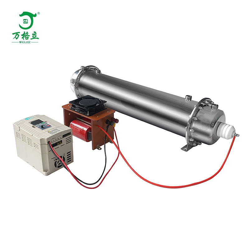
Name: Honeycomb 100 G/H ozone generator accessories (ozone inverter + high voltage package + ozone tube)
Model: FW-100G
Working voltage: AC220V/50HZ
Power consumption :15~800 W adjustable
Requirements: dry clean oxygen or air dew point ≤-20℃, operating pressure <0.9 Mpa
Ozone production: G/H 100
Requirements for ambient temperature :-10~40℃, ambient humidity :≤85% RH
Cooling water requirements: water temperature <35℃, pressure <0.2 Mpa.
Interface size: inlet and outlet nozzle and inlet nozzle are 4 points external tooth joint.
Special note: honeycomb ozone generator itself is a capacitive load, gas source pressure is different, capacitance is different, power will change according to the change of capacitance, so in different gas source devices, It is necessary to adjust the frequency of power supply to control the power output.
------------------------------------------------------------------------

Note: The terminal commands have been set at the factory, and they can be connected as indicated in the above figure during assembly. F13:02 frequency adjustment (0-10KHZ) F01:01 voltage adjustment [frequency/voltage adjustment can change the operating power/current, which has been set at the factory according to no-load working condition. If the operating power/current changes due to different working conditions on site, it is necessary to contact the manufacturer for adjustment] (the high-voltage package is installed on the insulation board, and the distance between the peripheral edges and the metal plate is more than 10cm, and the inside of the box is well cooled)
(High voltage package installed on insulation board and around the edge of the metal plate more than 10 cm from the inside of the box heat dissipation)
Installation instructions
First step: the ozone source and the high voltage package are installed on the insulation board (non-conductive material, more than 5 MM thick), the insulation board is fixed in the chassis, it should be noted that the high-voltage package is more than 20 cm from the metal case shell (if the high-voltage part is too close to the metal case shell, it may form high-voltage eddy current, which may affect the use or even damage), the high-voltage package needs to dissipate air heat (fan heat dissipation), the discharge chamber is installed inside the chassis, it can be connected with the chassis shell, the high-voltage line is connected to the terminal of the discharge chamber, and the high-voltage ground wire can be connected to the shell of the discharge chamber, Note that the high-voltage line should be more than 2 cm from other lines or chassis and must not be contacted.
Step 2: cooling water installation: if the discharge chamber is installed parallel to the plane, any end of the water or outlet can be installed, if the ozone pipe is installed perpendicular to the plane, the high-voltage line joint needs to face directly above, the inlet must be at the lower end, the outlet at the upper end. Check that leakage is not allowed after the water pipe is connected. Cooling water can be cooled with circulating water, or external water cooling, easy to install.
step 3: installation of air inlet and ozone outlet: an air inlet close to the high pressure connection end is an air inlet. the air inlet air guide pipe material such as silica gel, PVC, etc. the air outlet must be connected with antioxidant material (tetrafluorine tube, fluorine hose, stainless steel pipe, etc.). the gas entering the discharge chamber, whether oxygen or air, must ensure that the gas is clean and dry, temperature is not higher than 35 degrees, dew point below zero.
The fourth part: the potentiometer is installed on the control panel of the chassis shell, which is convenient for users to adjust and use. The main function is to adjust the output power of ozone power supply, thus changing the concentration and output of ozone output. Rotate counterclockwise and adjust small.
Step 5: check the line: after the high voltage line and the high voltage ground wire are connected to the ozone tube, try to connect the high voltage line with the shortest distance. Avoid high-voltage lines touching other lines or objects in the chassis. It is best to install and use silicone tube or PCV tube sleeve independently. Other lines, especially digital display electronic device connections and on-line signal detection connections, do not approach the high voltage part (high voltage package, high voltage line, ozone tube), otherwise high voltage may interfere with its normal use function.
Use of caveats
---------------------------------------------------------------------------
1、Check the equipment for damage or missing parts to ensure that there are no problems before being put into installation.
2、During the installation of components, please pay attention to light and light release to avoid damage.
3、After installing the equipment, check the air path, water path and circuit between the power supply to ensure that the power supply is correct.
4、Equipment installation to ensure that the high voltage does not leak to the chassis shell, high pressure danger.
5、It is forbidden to use in flammable and explosive places.
6、Ensure cooling water outlet temperature is not higher than 35℃.
7、Ozone outlet ozone concentration is high, human body do not contact ozone for a long time.
8、Installation of equipment non-professional personnel do not open the chassis, the general electrician must consult professional maintenance personnel can open the chassis.
9、If the equipment is used in water treatment, make sure that the gas-water mixing device can not return water to the ozone tube, otherwise it will lead to high voltage short circuit.
Routine maintenance of equipment
--------------------------------------------------------------------------
1、The installed equipment shall be placed in a dry, ventilated and clean environment with ambient temperature between -10~40℃ and relative humidity less than 85.
2、When the equipment is maintained, it is necessary to disconnect the power line.
3、The equipment can work continuously for 24 hours, but make sure the heat dissipation is good.
4、Wet towels for cleaning chassis must be dried and used. Do not splash water into the machine.