


Technical Specifications:
--------------------------------------------------------------------------------------------------
Name: 300G/H Ozone Generator Accessories (High-Voltage Control Power Supply + High-Voltage Transformer + Cellular Discharge Chamber)
Model: FW-300G
Operating Voltage: AC220V/50HZ
Power: 25~2500W Adjustable
Gas Supply: Dry and Clean Oxygen or Air; Dew Point ≤ -20℃, Pressure < 0.25MPa
Cooling Water: Flow Rate >8L/min, Outlet Temperature<35℃, Pressure <0.3MPa
Ozone Output: Using Oxygen, flow rate 55~65L/min, Ozone Output ≥300g/H
Using Cold Dry Air, flow rate 240~280L/min, Ozone Output ≥200g/H
Ozone Concentration: Maximum 150mg/L (Oxygen flow<5L/min)
Normal 95~110mg/L (Oxygen flow 55~65L/min)
Port Size: Gas inlet/outlet and water inlet/outlet ports are all 6-point external thread fittings
Operating Ambient Temperature: -10~40℃; Optimal Operating Ambient Temperature: -10~25℃
Operating Ambient Humidity: ≤85% RH (No condensation on smooth surfaces)
(Maintain >15cm clearance between high-voltage transformer edges and metal plates during installation)
Special Note: The cellular ozone generator is a capacitive load. Capacitance varies with gas source pressure, causing power consumption to change accordingly. Therefore, under different gas source conditions, the power supply frequency must be adjusted to match the stable pressure on-site to control power output. This prevents insufficient ozone concentration/yield due to inadequate power, or power supply burnout from exceeding rated power.
Product Structure Description:
----------------------------------------------------------------------------
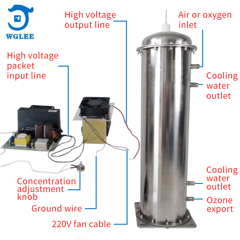
1. The 300G/H cellular ozone generator accessories consist of three components: ozone discharge tube, high-voltage transformer, and high-frequency power supply.
2. Cellular Ozone Tube Composition & Features: Cellular discharge chamber structure; internal electrode titanium alloy; external electrode 316L stainless steel; dielectric material high-purity silicon dioxide quartz tube; stainless steel flange and PTFE insulation; corrosion-resistant fluororubber seals. Water-cooled design with 304 stainless steel housing. Key features: High dielectric constant, low thermal expansion coefficient. Normal service life exceeds 20,000 hours.
3. Cooling water and gas ports use stainless steel 6-point external thread fittings for flexible adaptation to other connector sizes.
4. High-Voltage Power Supply Features: IGBT driven; soft-start (limits inrush current); over-voltage protection; power converter overheat protection; output short-circuit/open-circuit protection; anti-interference circuit; moisture/corrosion resistant design. Normal service life >20,000 hours. High-voltage transformer uses epoxy insulation with moisture resistance.
5. High-voltage power supply components:
A/ Potentiometer: Adjusts power supply output to control ozone concentration/yield. Clockwise increases, counterclockwise decreases.
B/ High-voltage & Ground Wires: High-voltage wire (red silicone, Ø5mm) connects to PTFE terminal on ozone tube flange. Ground wire (white) connects to ozone tube housing. Chassis must have reliable grounding (separate from lightning protection ground).
6. Cellular ozone tube ports are labeled: Cooling Water In, Cooling Water Out, Gas In, Ozone Out. Connect strictly according to labels.
(Maintain >15cm clearance between high-voltage transformer edges and metal plates)
DO NOT cut wires from low-voltage transformer to circuit board! If insufficient length, use terminal blocks for extension!!
Equipment Application Description
------------------------------------------------------------------------
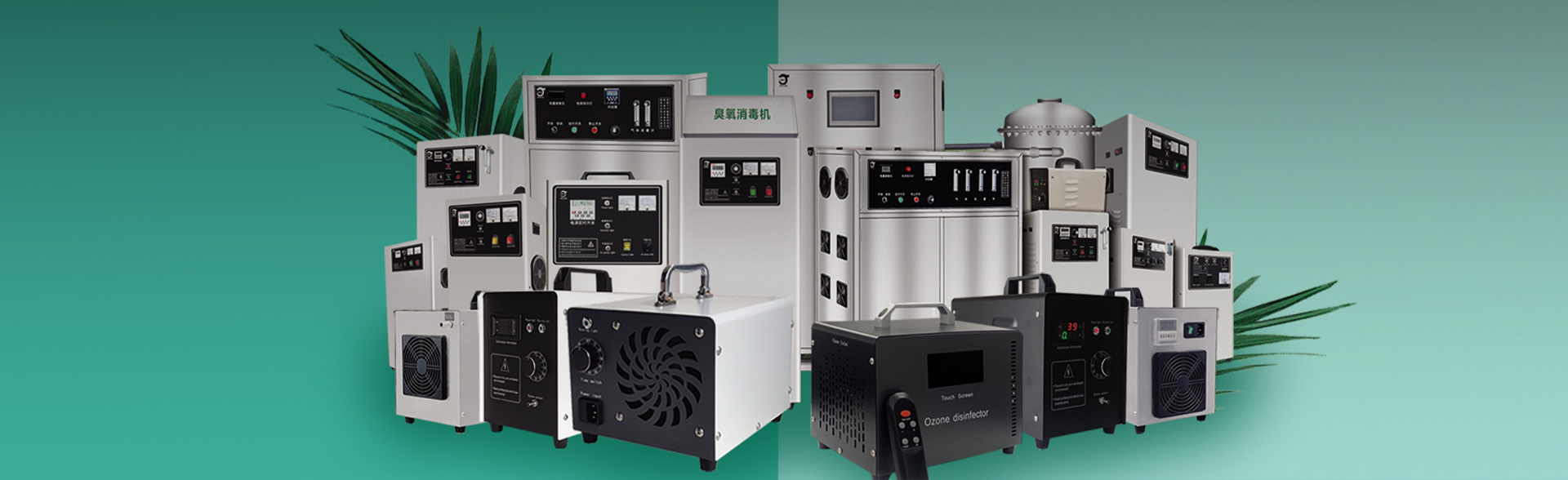
FW-300G ozone generator accessories are primarily used for ozone system assembly. Multiple units can be installed (e.g., 2 sets = 600g/H system). As core components of ozone generators, they accept oxygen or air sources for sterilization/purification applications. Widely used in water treatment, they are acclaimed for superior craftsmanship, electrical stability, and extended service life.
Installation Instructions
Step 1: Mount high-voltage power supply on insulating board (non-conductive, ≥5mm thick) secured in chassis. Maintain >15cm clearance between circuit board and metal chassis (prevents eddy currents). Ensure convective cooling for high-voltage transformer. Discharge chamber may contact chassis shell. Connect high-voltage wire to discharge terminal and ground wire to housing. Keep high-voltage wires >2cm from other components.
Step 2: Cooling Water Connection: For horizontal mounting, either port can be inlet/outlet. For vertical mounting: high-voltage terminal upward, water inlet at bottom, outlet at top. Water temperature ≤ ambient, flow >8L/min. Check for leaks. Recirculated or external cooling acceptable.
Step 3: Gas Connections: Port near high-voltage terminal is gas inlet (standard materials: silicone/PVC). Outlet requires ozone-resistant materials (PTFE/fluororubber/stainless steel). Ensure gas-tight connections. Supply gas must be clean, dry, ≤35°C, dew point<0°C.
Step 4: Mount potentiometer on chassis control panel for user adjustment.
Step 5: Wiring: Keep high-voltage connections as short as possible (factory length ~50cm). Prevent contact with other wires. Keep digital display/signal wires away from high-voltage components (transformer, wires, ozone tube).
Circuit Board Wiring & Debugging
Note: Factory-tested and calibrated. Users generally don't need readjustment. Technicians requiring specific parameters: Adjust gradually with power on while monitoring with power analyzer (not ammeter). Do not exceed 3000W. Set external potentiometer to maximum during adjustment.
Usage Precautions
---------------------------------------------------------------------------
1. Inspect for damage/missing parts before installation.
2. Handle components carefully; avoid impact damage.
3. Verify gas/water/electrical connections before power-on.
4. Prevent high-voltage leakage to chassis. HIGH VOLTAGE HAZARD.
5. Prohibited in flammable/explosive environments.
6. Maintain cooling water outlet temperature ≤40°C.
7. Avoid prolonged exposure to ozone outlet.
8. Only qualified personnel may open chassis.
9. Prevent water backflow into gas lines during water treatment.
Equipment Routine Maintenance
--------------------------------------------------------------------------
1. Operate in dry, ventilated, clean environment (-10~40°C,<85% RH).
2. Perform maintenance with power disconnected.
3. Suitable for 24/7 continuous operation with adequate cooling.
4. Wring out cleaning cloths thoroughly; prevent water ingress.