Technical Specifications
-----------------------------------------------------------------------------
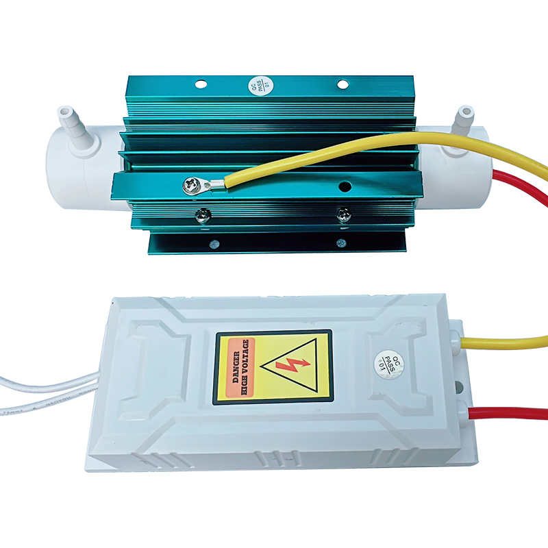
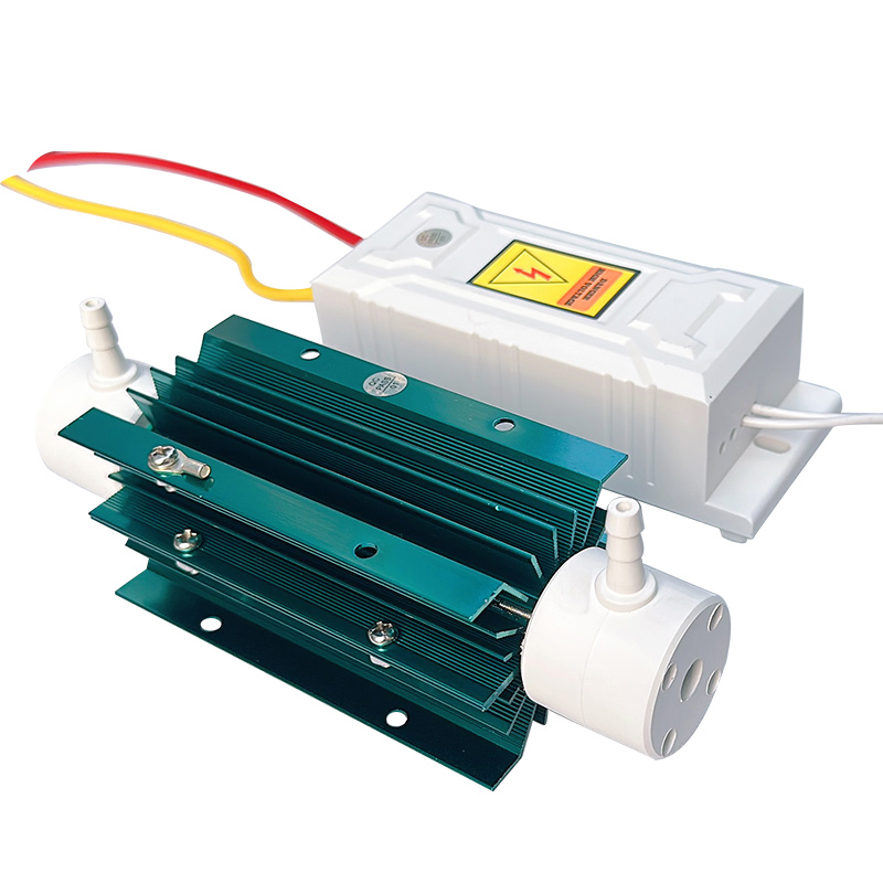
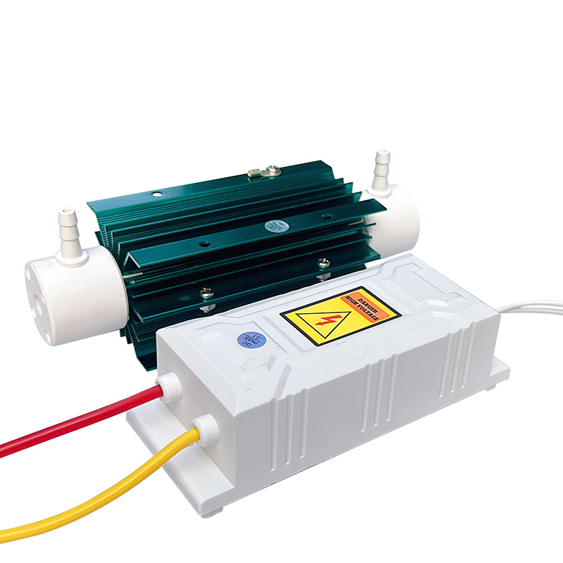
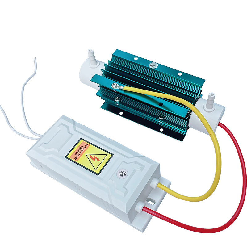
Name: 5G/H Ozone Generator Accessories (Power Module + Ozone Tube)
Model: KS-5G
Operating Voltage: AC220V/50HZ
Power Consumption: 50-55W
Cooling Method: Air-Cooled
Gas Supply: Dry and Clean Oxygen or Air
Ozone Output: 5G/H
Ozone Concentration: Oxygen Source 70-110mg/L; Air Source 8-12mg/L
Gas Flow Rate: Oxygen 1-2L/min Air 10-15L/min
Operating Ambient Temperature: -7~45℃
Operating Ambient Humidity: ≤85%RH
Dimensions: Ozone Tube (L*W*H): 172*56*53mm Power Supply: 146*55*46mm
Net Weight: 0.8 kg
Gas Port Size: ID 3mm OD 7mm Barbed Fitting
Mounting Dimensions: Power Supply Mounting Hole Spacing: 132mm, Hole Diameter: φ6mm
Ozone Tube Mounting Hole Spacing: 47*56mm, Hole Diameter: φ4.2mm
Product Structure Description:
-------------------------------------------------------------------------------
1. The 5G/H Ozone Generator Accessories include: Ozone Tube and Adjustable High-Voltage Power Supply.
2. Ozone Tube Composition and Features: Internal electrode made of 316L stainless steel, external electrode made of aluminum alloy heat sink, dielectric material made of quartz tube with ≥99.7% silicon dioxide content, combined with PTFE and fluororubber sealing components. External electrode is air-cooled. Key features: High dielectric constant, good dielectric toughness (resistant to damage during transport), low thermal expansion coefficient, pressure resistance up to 0.3 MPa. Normal service life exceeds 20,000 hours.
3. High-Voltage Power Supply Composition and Features: Vacuum epoxy high-voltage transformer; Main features: Moisture-proof, waterproof, suitable for harsh environments, circuit with anti-interference capability. Normal service life exceeds 18,000 hours.
Equipment Application Description
-------------------------------------------------------------------------------
The KS-5G Ozone Generator Accessories are core components of ozone generators. The gas supply can be oxygen or air. Used in applications requiring ozone sterilization or purification, such as space disinfection, deodorization, decolorization, and treatment of various source water and wastewater.
Equipment Installation and Operation Instructions
-------------------------------------------------------------------------------
Step 1: Mount the high-voltage power supply and ozone tube onto an insulating board. Secure the insulating board inside the equipment chassis. Important: Maintain a distance greater than 5 cm between the ozone tube/high-voltage power supply and the metal chassis shell (proximity may cause high-voltage eddy currents affecting performance or causing damage). Install the ozone tube within the convective airflow space inside the chassis, ensuring the fan directs air to the ozone tube's heat sink during operation for stable cooling.
Step 2: Gas Inlet and Ozone Outlet Installation: The gas ports on the ozone tube are not designated as inlet or outlet; either end can be used. Use silicone tubing or PVC tubing for the inlet gas line. Use ozone-resistant tubing (e.g., PTFE, fluororubber) for the outlet. Ensure gas-tight connections. The gas supplied to the ozone tube inlet, whether oxygen or air, must be clean, dry, temperature ≤45°C, and humidity ≤70% RH.
Step 3: Wiring Check: After connecting the high-voltage wire and ground wire to the ozone tube, keep the high-voltage wire connection as short as possible (factory length approx. 30 cm). Cut wires shorter if needed to avoid contact with other components. If possible, sleeve the high-voltage wires with silicone tubing (ID 8mm) to enhance insulation. Insert the spring-equipped high-voltage wire into the center of the ozone tube. Keep all other wires away from high-voltage components (transformer, high-voltage wires, ozone tube) to prevent interference.
Ozone Tube Structure Diagram:

High-Voltage Power Supply to Ozone Discharge Tube Wiring Method:

The area between two dashed lines represents the inner space of the ozone tube's stainless steel internal electrode. Insert the spring-equipped high-voltage wire and use a screwdriver to position the spring clip near the center. Connect the other high-voltage wire to the aluminum alloy heat sink of the ozone discharge tube.
(CAUTION: Do not cross the two high-voltage wires)
Usage Precautions
-------------------------------------------------------------------------------
1. Upon receiving goods, inspect for damage or missing parts before installation/use.
2. Handle components carefully during installation; avoid drops/impacts.
3. Before powering on, verify gas lines and electrical circuits.
4. Ensure installation prevents high-voltage leakage to chassis. HIGH VOLTAGE HAZARD.
5. Prohibited in flammable/explosive environments.
6. Maintain effective convective cooling. Ozone tube temperature must not exceed 60°C.
7. High ozone concentration at outlet. Avoid prolonged human exposure. Wait 20 minutes after shutdown before entering ozonated spaces.
8. Do not open chassis unless qualified. General electricians must consult professionals first.
9. For water treatment, prevent water backflow into gas lines to avoid short circuits.
Routine Maintenance
-------------------------------------------------------------------------------
1. Operate in dry, ventilated, clean environment (-7~45°C,<85% RH).
2. Perform maintenance with power disconnected.
3. Regularly clean ventilation grilles if dusty; reinstall properly.
4. Suitable for 24/7 continuous operation with adequate cooling/ventilation.
5. Wring out cleaning cloths thoroughly; prevent water ingress into equipment.